Off grid solar
Revised 12/12/2015
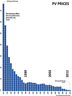
Back in 2002 we did a cost benefit analysis on PV payback, and the numbers just didn't add up. But since that time there has been a factor 5 drop in PV prices, thanks to Chinese (and other) manufacturers having ramped up in a big way in service markets created by FIT tariffs in Europe. This trend of declining prices is sometimes known as the Swanson effect. Is it too early to start believing Kurzweil's prediction that the world will be 100% solar by twenty twenty something?
Our new rural block had no services at all, and it looked like solar was a timely option for us. But before we got too deep down the rabbit hole, the quote for a mains power connection to a pole 50m away came in at $21K. It is pretty clear that the power companies are now charging full cost for new rural connections because they too can see the potential of distributed renewable energy systems. But for us, it was glaringly obvious that solar would pay back on the very first day, and most likely never look back.
Looking further into this, we discovered a whole new landscape. Before, there were 80W panels, heavy reliance on generators, propane, and solar hot water. With the current cost of PV, it is now cheaper to add a few extra panels than to mess about with generators. And PV in some circles is being called the new solar hot water. At the current price it costs about the same to heat your water using PV as it does to buy a good quality SHW system. However with PV there is no plumbing, no leaks or frost issues, no pumps or temper valves, no maintenance of any kind. So, where do we sign?
The result of having an array sized to cover the worst time of year, is that you get quite a bit of spare power at peak sun times. Therefore it makes sense to divide your loads up into base loads and opportunity loads. Our base loads are refrigeration, water pumps, computer gear, lighting, as well as sundry occasional appliances and power tools. All the usual stuff, washing machine, iron, sewing machine, juicer, blender, power tools etc. The spare power is to be dumped straight into the hot water cylinder.
Designing and installing a system like this requires a ton of research. With help from friends, NAWS and a background in electronics, we put together a power use budget, an energy production model, and a schematic design.
Component Overview
Because you have to replace them more often than any thing component, batterys are the archiles heel. If you consider that a 10kWh battery with 2500 cycles to 25% DOD will deliver 6250kWh over its lifetime, and costs 2500 dollars, then that works out to = 2500 / (2500 x 10kWh x 0.25) = $0.40/kWh. Ignoring all the other system costs, thats already more than what youll pay for grid power.
For these reasons off grid designs tend to hinge around the battery. While the various lithiums and some exotic newcomers like the Aquions are emerging, lead acid is for now still the field tested industry dominant chemistry. There is some good things about lead, such as very very high recylcability, and the fact that the chemistry enjoys 100% SOC as much as we do. Until the various ion chemistries with their higher up front costs prove the calendar and cycle life that is so critical to their payback model, the industry's view is that flooded lead acid batteries for now (perhaps only just) offer the best value for money.
Use only true deep cycle batteries, generally in the GC2 or L16 format. With lead prices on the rise, the old 'days autonomy' model is now more or less history, and with the battery as the weakest link, you just want to cycle the battery in its happiest, longest life band. Which is the top quarter of its capacity.
The NAWS 'rule of thumb' formulas, (assuming an AC demand of 3kWh/day) are:
- battery size is determined by a 25% daily DOD, thus: 1/0.25 x 3kWh/d x 0.85 inverter efficiency / 24V = 500Ah.
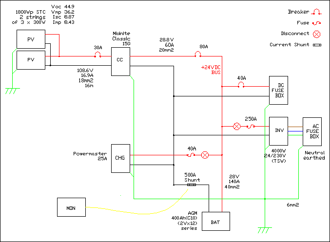
- array size is determined by being able to acheive a 0.1C peak charge rate, thus: 0.1 x 500Ah x 1/0.77 CC/PV derating x 24V = 1560Wp
- inverter size is determined by not exceeding a 0.25C peak discharge rate, or 0.25 x 500Ah x 0.85 x 24V = 2550W
Trading off their shorter life, VRLA/AGMs offer lower internal resistance, which means that you can increase both charge and discharge rates. We ended up rounding the battery down to an even 400Ah AGM (because we dont use much power after dark), and rounding the array up to an even 1800Wp (which gives us a little more freedom from the genset backup that is assumed in the 25% daily DOD model). Round the inverter up to the ubiquitous 3kW Outback. That results in a 0.15C charge rate, and a 0.35C discharge rate.
Permormance Modelling
Second after the load budget, you need good solar insolation / irradiance data. We got this from the NIWA Solarview website. This data is excellent because it takes into account not only theoretical sunshine hours based on your location and array tilt, but tempers it with real world weather data from your area, as well as any significant landscape shading using a 3D DEM model. The down side is the nearest weather station might not be very near. Ours was about 15kms away. Anyway if you trawl around in there, you can download hourly, daily and monthly data for a 'typical metereological year', in a highly usable form.
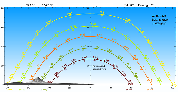
NIWA Solar View Site analysis
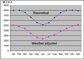
A brief look at the monthly irradiance data gives this graph of the monthly averages for solar watts per square meter per day (or to get hours sunshine STC, divide by 1000). So 2.5 hours in winter, 5 hours summer. Given that off grid systems only store a few days of power, you can learn a lot by doing a daily analysis as well. This is based on the net daily balance model used in rainwater tank design. To the existing battery state of charge (SOC), add the days production, subtract the days loads, get the new SOC, then repeat for each day of the study year. With solar you of course need a half days storage to cover the night period, but the principle is the same. Here's what the daily analysis looks like:
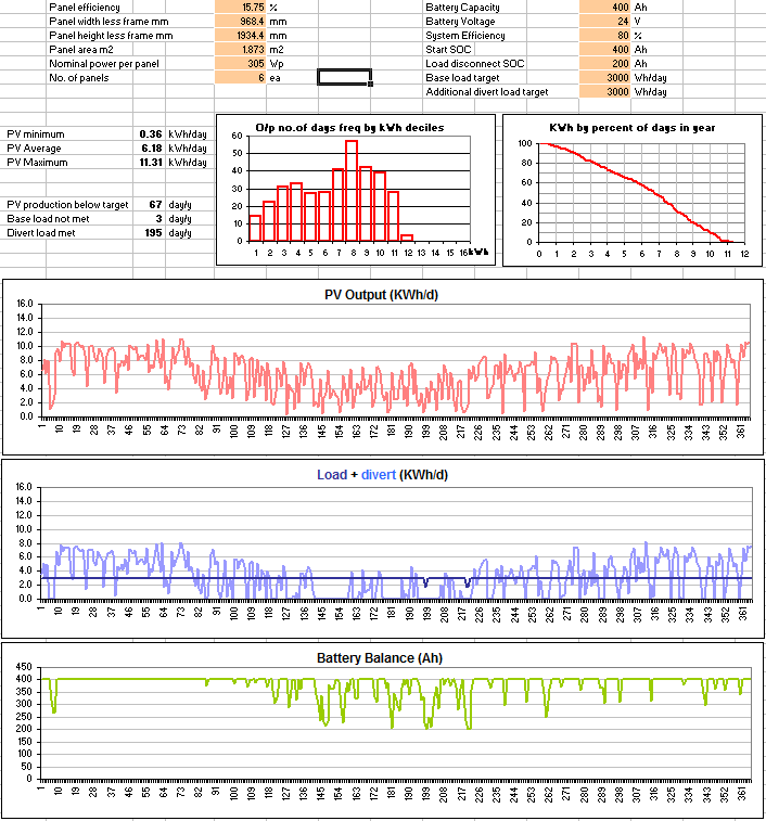
That analysis starts to give us a real feel for what the system will do. According to the daily balance model there's only 3 days in the year when the system wont deliver the target base loads. 3kWh/d isnt a huge amount, but having lived on that previously we knew we could do it for a while until we add winter hydro into the mix later on. For the other numerically obsessed out there, here's the spreadsheet.
The system components will now be looked at in more detail.
Solar Panels
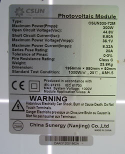
Having decided we needed 1.8kW of PV panels for the initial stage, and wanting the total number of panels to be divisible by 2 or 3. we ordered six 300W panels from a small online RE supplier. They are manufactured by CSUN, who are a chinese government ownded tier one producer. 25 year warranties dont mean very much if you consider that the industry is now a low margin, cost cutting driven one. There are plenty of panel failures, and the biggest manufacturer Suntech recently went under. But, rightly or wrongly, choosing a name brand panel seemed like small peace of mind. Tier one producers design and make their own cells, as opposed to just being an assembler. We paid a little extra for that, NZD1.90/W compared to 1.50/W at the time for the cheapest no-name panel around.
300W panels are physically a bit of a handful. They are two meters by one meter in size and weigh 24kg each, and so freight can be tricky to arrange in small quantities, ie anything less than a full pallet. We ended up driving 400km to pick them up ourselves.
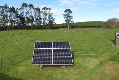
Ground Mount
Because our roof is wind exposed, facing the wrong way and not particularly strong, a ground mount seemed like a good idea. And we have plenty of space.
Its a cheap design comprising some pressure treated pine, home made scrap angle iron brackets, and plenty of bracing. The rack is designed to be relocatable, as we dont know where the house will ultimately be built. So its all bolts and mecano. Total cost for the rack was about $250 and took 3 days to build over the summer break.
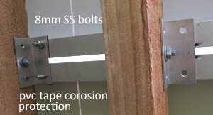
Being in a high wind zone we also opted to use the secondary mounting rails as well, which gives some redundancy to allow for warping and splitting type failures. The trick to getting all the holes to line up is to make a pair of jigs made from some 20x10mm wood with holes and bolts fitted at the horizontal and vertical spacing. For sqaureness i used a large plywood offcut, as plywood is always square. The aluminium PV brackets were attached then the panels.
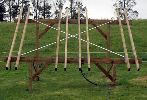
Rack completed
|
Rafter mounting bracket |
Construction detail |
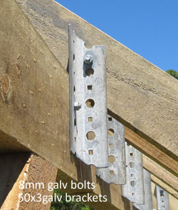
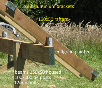
Lastly some attention to keeping dissimilar metals apart, and treated timber away from aluminium. Wide PVC tape is what we used, but these will need periodic inspection for corrosion. Choose a calm day to mount the panels. You dont need to cover the panels, but wiring them up in a certain order (below) will avoid getting a shock off them.
As for the angle, theoretical models, show that depending on your needs a summer bias increases annual yields. However if your design is premised on peak demand as ours is, then a winter bias is in some ways more appropriate. But we eventually went with the latitude, fixed at 39 deg. from the horizon. If and when we add hydro into the mix, we may lower the angle.
PV mounting brackets
Cable
We then worked out the required home run cable size. The array is some distance away so we need to check the cable loss. There are good online cable loss calculators but its easy to work it out yourself. The formula is:
R (ohms) = 2 * cable length (m) * resistivity of Cu (0.000000017 ohm.m) / cable area (mm2) * 1000 * 1000
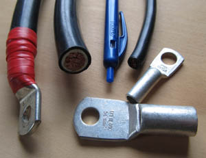
The kind of cable required isnt terribly common, at least not at the local hardware store. Its a heavy gauge single core cable with lots of smaller strands, and a heavy duty insulating sheath. Like these General cable products. They come in 16,25,35,50,70mm2 and all the way up to 630mm2. But 16-70mm2 are the ones most commonly used in solar systems. Its surprising bendable for such hefty wire.
There's three things its good to understand about cable sizing.
1. Firstly you design for two important wire characteristics. Ampacity (also here) is a measure of how much current a wire can safely carry, without melting, and setting your place on fire. You'll see deratings on the charts depending on the thermal insulation of materials near the cable. If you really want to know the cables limits, just for kicks look up the fusing value, that's the current that it literally melts and open circuits. We wont be doing that today. The temperature rating of the insulation is also interesting to us, at least 75 degrees C, usually 90. The other characteristic is the resistance from the point of view of its voltage drop. When PV costs so much you'll not want to waste its energy. But in general if you design your cable size to lose less than 2 percent of the delivered wattage, then youll have the resistance and ampacity well covered.
Choosing the PV cable for our array
2. With electricity, if V=IR and P=VI then P=IR. ie doubling is sometimes not doubling. A good illustration of this arose when deciding to use 2 strings of 3 panels or 3 strings of 2, or more dramatically to use PWM or MPPT. With PWM I'd need 6 strings of one panel. That would be what, 3 times more cable than 2 strings?. No, its 9 times more cable.
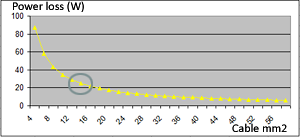
3. Thirdly, there is no such thing as a perfect cable. The graph at right shows that too smaller a cable has nasty effects on your cable loss, but after that increasing the kilos of copper is an exercising in ever diminishing returns. With copper rapidly becoming the next precious metal, you just want something past the knee in the curve and not much more.
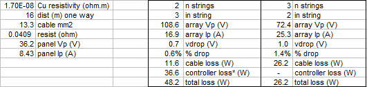
To further complicate things, MPPT controllers are more efficient when the PV voltage is just a bit higher than the battery voltage, ie, 24v for 12v batt, 48v for 24v batt. Higher than that they reduce in their conversion efficiency. Notionally 2% percent additional loss per extra nominal battery voltage*.
So on the one hand the higher the voltage the less copper investment, but the more controller losses. When it boiled down to it, we had two choices of PV configuration, 2S3P or 3S2P. Obviously the CC is limited to 150V, and above 125V an extra layer of regulatory red tape kicks in. From a safety point of view 125VDC is more dangerous than 125VAC, because it doesn't zero-cross. Lets be careful out there.
The one remaining factor was string fusing. In order to prevent array fires that occur when a failed string shorts, multi string arrays need string fusing. Technically three or more strings need string fusing (you need string fuses when the Isc from n-1 strings exceeds the sticker series fuse rating of a single string). In our case the sticker rating was 20A. Isc for two strings is 18A, so in this case 3 strings could never blow the string fuses. String breakers are however recomended for array isolation. In the end, we went with 3 strings of 2 , for additional safety, and lowest overall power loss.
PV wring
The panels come with 4mm2 fly leads and permanently affixed waterproof MC4 connectors. To avoid messing with the warranty, you need to get some pairs of MC4s, some 4mm2 PV rated (UV/abrasion resistant) cable and a lightish duty crimper. Not the super light automotive kind, but the next kind up. Failing that measure it all out and get a pro to crimp them. Alternatively you can buy mc4 extension cables and cut them in half, if you can find them the right length.
Work methodically keep all the different polaritys clear in your mind. And, that the string output voltage can kill you. Tape the MC4s together side by side like they were connected, route the cabling and terminate each string to the combiner. That way you can wire during daylight without danger, and all you have to do is clip the MC4s to enliven the array.
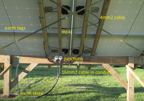
PV wiring
Try to keep each pair of positive and negative wires close together and equal in length right up to the panels. If strings are diff lengths doesnt matter much as the panels themselves have high effective resistance. Panel variance will always result in uneven string balance. Secure the wires with UV resistant cable ties or better.
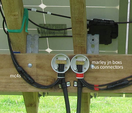
PV combiner
Array grounding
This is complicated, and there are two main reasons for it. Firstly in the event of a panel hot to frame short, the system needs to be able to deenergise the exposed voltage in case someone touchs the frame (this assumes a grounded system, see below) and gets a lethal shock. Therefore the array frames need to be tied into the main system ground bus to allow the current to effectively clamp to zero, via the ground return (there isnt enough current to blow PV fusing).
The second reason is lightning protection. Although you might say that grounding the array frame is somewhat like painting a big 'hit me' sign on the array, given that its grounded as above, then you need to provide as short and a direct path to ground as possible.
For the latter reason the rack has a dedicated earth stake. However where a system has muliple ground rods, they need to be bonded together to prevent votlage differentials occuring during lightning events, and, you also need a low resistance ground bus connection to deenergise the array. By code this generally means running an insulated ground wire together with the home run cable. However another way is to use a buried bare solid copper wire (of sufficient guage to resist damage). This bond also forms part of the earth system and enhances the connection to ground at both ends. However if there is any doubt about the long term integrity of this wire, a second insulated wire should also be run. My plan is to use recycled half inch copper water pipe.
Since panel to frame shorts are not so likely, the lightening factor is worth taking some care over. Use large strand size, corosion resistanct connectors, take the most direct route, avoiding bends where possible, especially sharp bends which lightning does not do. For the stake connection i prefer crimped lug and a nut and bolt, with a liberal coating of grease.
To give you an idea about the murky nature of all this, one of the scenarios the code envisages is where there are dual untied grounds, if you use a non-double-insulated power tool earthed to the system earth bus, on an extension lead out at the array, you might get a ground differential caused by the resistance of the ground that in rare cases may be dangerous
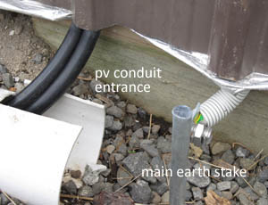
PV cable entrance
I still have the MNPV3 combiner to install. As money was tight at the start, I've been going back and fixing up my intial shortcuts. For the temporary combiner i used a couple of pvc inspection junctions, and a pair of brass terminal blocks out of an old switchboard. Leave all the mc4s disconnected until the rest of the system is commissioned. Only connect the MC4s when theres no current available, ie breakers are off. This is to protect the sliver plating in the MC4s (be sure to get quality MC4s).
The temporary setup is using alkathene conduit run on top of the ground. I will bury a 4 inch drain coil, and feed the conduit through when i get a chance.
Charge controller
It didsnt take a huge amount of thought to chose the Midnite Classic 150 lite controller. The reasons are these:
- cutting edge technology, cult status in the industry
- unlike outback you dont need a whole bunch of accessory grear, the classics network in a daisy chain fashion
- can run 94 amps of PV if we decide to add another pair of panels.
- two aux ports built in
- fans that dont sound like a freight train, and only come on occasionally.
- built in ethernet and usb, a deal clincher around here, where computers are the thing.
- user updateable firmware, many monitoring options.
We have been happy with it. It was easy to install and works like clockwork (a bit unusual for anything powered by a computer). I guess i wasnt all that keen on having to expose the entire internals to the light of day to wire it up, but that just reminds you that the entire undertaking does require your attention. Mistakes are likely to be unforgiving. Midnite also have a battery shunt monitor addon called WbJr, which is be able to calculate battery and house load current and SOC quite accurately.
Depending on whether you have lite or full, read the manual fully, and make the initial configuration settings, in my case, AGM, 24V, IP address, and manual eq. Thats it. The rest you do once its powered up. Download the local app, and install it on a computer.
Batterys
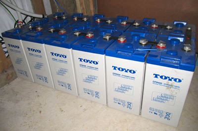
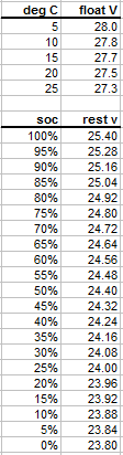
Our batterys are 400Ah AGM VRLA 2 volts cells. One string of 12 for 24v nominal. Generally flooded/wet cells are considered best for off grid as they are more robust, you can test the SG, and equalise to maintain battery health. The Toyo branded (chinese) AGMs dropped into our lap via a guy who imported a pallet and only needed half. They were half price, so at least if they dont last it hasnt cost us much. The cycle life expectancy for these is 3200 10% cycles 1500 50% cycles. The charging parameters are a little lower than the classic defaults for AGM. Absorb is 28.2V, and float is 27.0 float, with temperature compensation of 3mV/degC.
Parallel battery strings can work if you dont get too carried away, but the keep-it-simple rule applys here. Use a single string if you can. 24V is a minimum, 48V is better. Dont mess about with 12v regardless of what low voltage gear you might have. Less amps. Less heat, less loss, less wire, less gear. All you ever wanted to know about batteries is at batteryuniversity.com.
Just to give an idea of how seriously you should take a battery bank like this: the spec sheet lists the internal resistance as 1.5milliohm. Put another way, shorted that will deliver in the vicinity of 18,000 amps. I have built a temporary cover for the bank until it gets a proper home. You dont want to accidentally drop something metal on the battery, that would not be pretty. Kids, cats, etc. I once worked in a battery lab, and saw some pretty educational fireballs.
They are 30kgs each so nearly half a tonne all up. As discussed AGMs are more liberal with their charge rate, but for any battery 0.1C is always a good place to start. In our setup 0.1C is 40amps. On an 'average day', the array produces 6kWh, and is able to fully charge the 10kWh bank from as low as 40% SOC.
Peukarts law says that the higher the discharge rate the lower the capacity of the bank. These batterys are rated at a C10 rate (while most deep cycle batterys rated at C20). You might even say that the C100 rate is closer to our use pattern. C100 for that bank is around 520Ah. As you cant use the bottom half capacity too often without lowering the service life, which takes your effective capacity to around 260Ah at C100. For our base loads of 3kWh/d, that should give us 2 days buffer assuming zero sun, or about 4-5 days in real world bleak conditions. It takes a very dark day to stop the panels producing, and most grey days still produce more enough to cover the base loads. With enough panels, its the brief bright periods during bad weather that do the job. Thats the advantage of AGM and overpanelling. The daily perfomance model confirms this.
The other advantage of AGM in practice is not having to water the batterys. The main difficulty with AGM is there's no fool proof way of determining their state of charge. Battery monitors are good when combined with some common sense, and getting familiar with your morning 'rest" voltage. Remember all lead acid batterys must be 100% fully charged regularly to prevent sulphation.
With all the breakers off, connect each battery cell carefully using the supplied nickel plated links, to the correct torque. Leave a bit of an air gap between the cells. Need it be said that the polarity is super, super, super critical there? Get it right first time, be careful with the spanner!, and have a safety person nearby.
For the battery cable hit the voltage drop calculator. You want this cable to be short, and fat. Becasue its short you can afford to use a thick cable even if it is like 20 dollars a meter. The inverter will at times draw hundreds of amps and you dont want much sag there at all. This also ensures that the charge controller has an accurate idea about the true terminal voltage, so that it can make charge decisions properly. I went with 1m of 50mm2. Thats 0.2V loss at the inverter breaker rated 175A.
Inverter
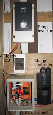
Early setup
I was warned early on that bigger is not better, and that a 4 or 6kW inverter can be a dangerous thing. Without vigilance, one hour at full capacity can draw the battery bank to zero. And the bigger the inverter the higher the tare loss. Tare loss is the power that the inverter draws doing nothing. Some inverters have a 50W tare, which means that over 24 hours = 50W x 24 = 1200Wh. Thats more than a fridge, and so you had better have a decent array and battery to support a large inverter. Also be aware that the sleep mode on these things, will not likely be of any use to you. If you have an electric toothrbush, a cordless phone or an internet modem, any one of those will defeat sleep mode. A configuration that can work is a larger inverter in sleep mode for large items, and a small inverter for everything else (on seperate circuits of course).
The other key lesson is that with inverters, you get exactly what you pay for. There are no shortcuts to the reliability and safety of a name brand UL listed for hardwire inverter. I, like many before me, tried out those cheap chinese inverters you find on ebay, and they just dont last. Blew up in the first week. If money is tight, then look at the mid range inverters as a temporary solution. Brands such as: Cotek, Samlex, Exceltech, Xantrex and Powermaster. But ultimately youll end up with one of the big five: Outback, Magnum, Schneider, Victron, or SMA. They are purpose designed for hardwire, and give you the reassurance you need and want for full time off grid living.
We started off with a borrowed 1100W Steca Solarix PL1100. It worked really nicely, was quiet, double insulated (which simplifys grounding) and the standby draw was an impressive 10W. The main problem with it was that it wouldnt run the vacuum cleaner, or circular saw. But it has been a good exercise is experiencing exactly how small an inverter we actually live with. By hunting around yard sales and junk shops, you can find older appliances like irons and kettles that draw significantly less power than the modern equivilents.
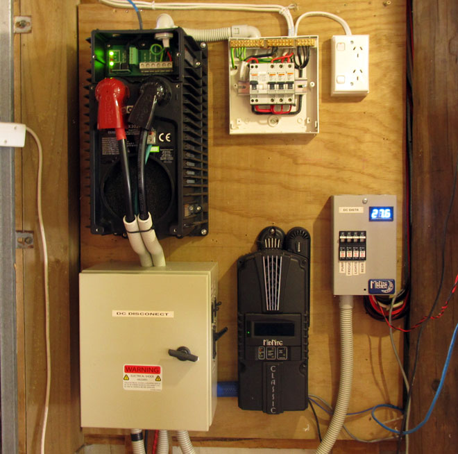
However after about 18 months we finally broke down and bought an Outback VFX3024E. We did save some money by bringing it in from the states. I go into this some more elsewhere. They are really heavy and the tare is a pretty reasonable 20W. We dont have a Mate (because theres no genset), but we do use it with a remote on off switch (in the kitchen), to turn it off at night. The fan ramps up with load but is off most of the time. Wiring it up is not easy due to its odd form factor. The thing is deep, and both the AC and DC terminals are mounted far from the wall. Really if you use this inverter one of the midnite e-panels is the way to go. I was by then commited to our home made disconnect, and used pvc conduit to connect the inverter to the DC disconnect and the AC distribution box.
Power wall gradually coming together
DC Disconnect
Our DC disconnect cabinet was cobbled together from various bits for a DIY solution. I didnt research the disco properly, and doing it again i would undoubtedly have gone wiith Midnite's MNDC and its excellent manual. Trying to cut costs I naively accepted some solar outfits recommendation on the blue seas inverter breaker, not knowing that these have a poor reputation in the industry and a tendency to explode. Use either properly rated T class high interrupt fuses or better yet the Carling heavy duty breakers. With the power of hindsight a couple hundred bucks is a sweet deal.
Select breaker ratings on the principle that fusing is designed to protect the cable from melting. 90 volts DC is about exactly what you find inside your average arc welder, and I am not stretching the metaphor, by saying that DC arcs are an excellent way to start a fire. This means you can start an arc either between plus and minus, or from a loose inline connection.
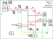
Schematic drawing larger image
One thing to note is that the polarity sensitive DIN rail breakers are in the process of being phased out. Reversed they are dangerous eg see here or here. Any breaker for the controller goes positive to the battery, somewhat counter-intuitively. In a fault condition the battery will always be more positive even if in normal conditions its the other way around. The array output is current limited, so that breaker is there for worse case scenarios, like a dead controller.
16mm or 25mm wire between classic and the positive bus. Youll need crimp lugs, and a proper multi ton crimper or a friendly someone who owns one. Take it down to any automotive electrical place and they will do it for you for some beers. Color code religiously. Heat shrink is our friend. While doing any work on the cabinet positive bus, disconnect the battery negative. Always.
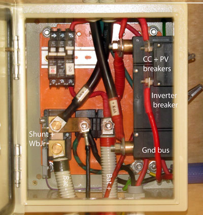
Understand which parts of the disconnect are unfused, in this case the central red area surrounding the positive bus post. Ive kept this area uncluttered. You cant usually use a fuse on the battery line because its considered an ignition source (less than 500mm from battery). So definately use extra conduit for protection and fire safety there. Beware many battery switches and fuses are not robust enough to handle large continuous currents as is found running into an inverter. Research any product you use carefully, ask for second opinions from the pros. There's too many instances of blade fuses and flakey battery switchs around that are frankly dangerous. With DC there are much bigger arcs when starting and stopping current flow. This can weld many common switches and fuses in the on position, the exact opposite to the devices purpose.
For the AC side here we use the standard plastic breaker boxes. Fit one RCD, and as many local circuit mcbs as you need. Unless you have a huge inverter the mcbs arent going to do much, more like isolation switches is all. The neutral is securely grounded before it enters the rcd. Wire tidily, cleanliness as they say is next to godliness.
Grounding
Also controversial is dc grounding. In NZ its more uncommon, but North American practice has it that you bond the DC negative to ground. The usual method is a solid bus bar link, however modern regulations now promote the use of electronic ground fault interruptors, along the lines of the one in the Classic (which, at one time we used, but now do not). The pros agree the new regs have shortcomings in that after the ground fault trips the system becomes ungrounded and could expose high array voltages if you did not notice that it had tripped. Others say that an ungrounded DC side can permit a static build up that can damage appliances connected on the DC side. In any event grounding the DC side means you can just fuse the positives, but if you dont, both postives and negatives must be fused. In NZ the regs currently say that the DC side must be gronded over 125VDC.
The AC side must always be grounded under the MEN protocol, and you want a single ground to neutral link. While i have wired up the AC distribution board, we will get it signed off at some point by a sparky, which is in most jurisdictions required by law.
As for lighting protection, it's a bit of a dark art. But here is what ive managed to gleam:
- keep all DC and AC wiring as short as possible, inside and out, if possible give the occasional half twist to help reduce their antenna effect.
- the flywheel effect of the battery bank should protect the main DC bus and anything connected close to it.
- the classic contains a limited protection (around 3kV) for its PV inputs.
- adding SPDs to the PV and the AC side is increasingly considered a good thing.
- a really good main earth connection. Either a single rod pounded deep into wet compact soil, or concrete slab rebar can also work. Use multiple stakes or bare copper cable in trenches if there are any issues with light or dry soils.
- i think the consensus is that long incoming cables such as any mains AC, or generator, and the telephone are the biggest risks.
- on the subject of inverter failures opinions vary, but sources say inverters die mostly on the AC side.
- bringing array frame earths into the building to access a single earth is a bad idea
- keep sharp bends out of the earth cabling.
- ground everything metal to a single ground bus, and tight single (corosion resistant) connection to the main earth stake.
- some of the above is inherently contradictory, Good luck.
Commissioning
Arm yourself with DMM and a DC clamp meter. Make sure all the breakers are off, mc4s off, then screw everything up nice and tight. Connect one mc4 string at a time checking polarity and voltage on each string, checking with DMM that youve got them all right. Dont necessarily trust the pv labelled polarity as mistakes do occur.
Inside, carefully resecure the lid back on the classic. Check the PV voltage and polarity at the PV breaker. Remember the PV bus is hot, treat it like you treat AC. Check the battery polarity at the main bus. Continuity test for shorts across the main bus, and both dc and ac load termination. Triple check from the schematic until you are 100% satisfied. Take your time. When ready activate the breaker between battery and classic. The fan will fire up briefly as it boots, then stop and the indicators will flash and progress quickly to standby. So far so good.
Now turn on the pv breaker. Classic will go into bulk and start charging, assuming the sun is out. Use the clamp meter to check the pv current, the controller and battery current until all makes sense.You should be seeing more maybe twice as much current coming out of the controller as goes into it. That's what a buck converter does. Now turn on the dc loads breaker, if you have one. Finally once everything is confirmed settled and good engage the inverter breaker. The inverter will wake up and go into standby. All being well you are in business.
Maintenance
Early on i kept a log book, noting the battery voltage and temp each morning, and cell balance occasionally. I also noted any days the bank never floated. Most days the controller is in float by midday. We have a LED panel voltage meter which shows the battery voltage. Rest voltage corelates with SOC to a reasonable extent, however true rest is unlikely to occur in an off grid set up. The only load overnite is the fridge cycling, its a reasonable guide once you get familiar with it, and the effect that temperature has upon it. On an average day the bank will start the day at 24.9v. During a period of protracted rainy weather in the middle of winter, it might go 3 days without floating by which time rest voltage is as low as 24.4V. Thats about 50% SOC. If it goes much lower than that, then you are doing something wrong. When Midnite released the Whizbang Junior battery shunt monitor, we quickly put one into service to correctly terminate absorb, in addition to giving really good monitoring data via the local app and later via the Blackbox (see elsewhere).
2015-12-12
www.zoneblue.nz/cms/page.php?view=off-grid-solar


